Today's theme is: tactical redirectionWe went into this session with a plan: install and adjust the rest of the valve train, and then, time permitting, start putting on the outside stuff. It didn't quite work out that way...
First step: the lifters.
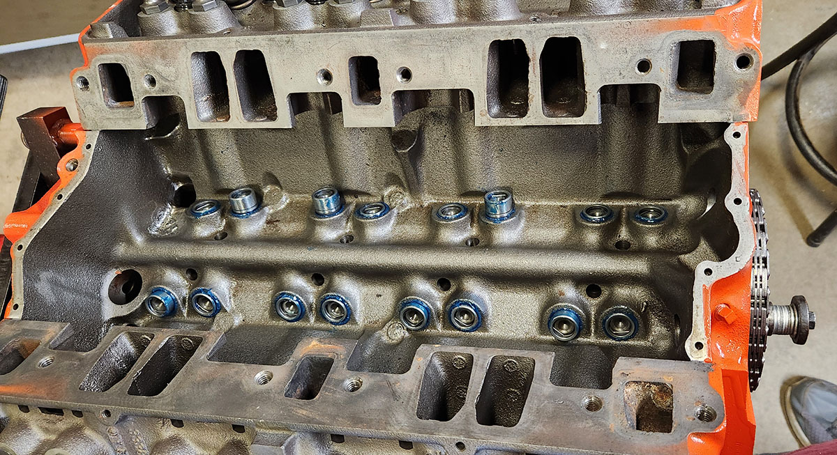
In an overhead-valve engine like this one, the lifters are the parts that actually interact with the lobes on the camshaft. You can see here that some of them are up, indicating valves that are open at the point in the cycle where the cam is currently sitting--except for those two at the left end of the upper row, which got stuck partway in and had to be persuaded a little after I took this photo.
The holes in the top reveal these to be hydraulic lifters, which, in addition to their main job of pushing the valves open via the pushrods, also pump oil up through said pushrods to more effectively lubricate the top end. There are fancier modern cam/lifter combinations available for these engines that involve rollers on the cam lobes and all sorts of friction-reducing trickery, but since we're only doing a mild performance build, we don't need to go to that kind of expense.
The next step from here would have been sliding in push rods, then attaching the rocker arms up top and getting everything adjusted, but here we ran into a problem. We have no fewer than three sets of these things kicking around, all salvaged from other engines (including the one this block came out of!), but after cleaning and inspecting samples from all three, we realized that none of them is in good enough shape for this build.
Some would be OK for a true shoestring overhaul, where you're just sprucing up a tired engine with some better parts and whatnot. If we combed through all 96 of these old parts, we could probably come up with 16 push rods and 16 rockers that would be fine for a while. But we've sunk a lot of money (well, OK, Dad's sunk a lot of money) into this build, even though we're not going crazy with the performance mods, and after discussing it at length, we decided it didn't make sense to cheap out now and use old valve-train parts that might let us down. Even in an older-style engine like this that doesn't have the modern problem of valve/piston interference, if you have a pushrod bend, or bust through the rocker arm, or the like, it does Bad Things to your engine.
So, that part of the build is on hold until the latest parts order arrives, and then I'll be finishing up the valve train with all new parts.
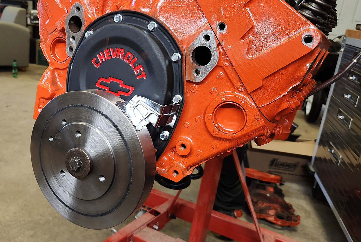
This decision could have shut us down for the day, but in a situation like this, you adapt. We spent part of the remaining time doing research for a later part of the project, which I'll save discussion of until we get to it, and then spent the rest of it doing what we could with the other stuff we had on hand, namely: buttoning up the front of the engine. This started with: the new timing cover!
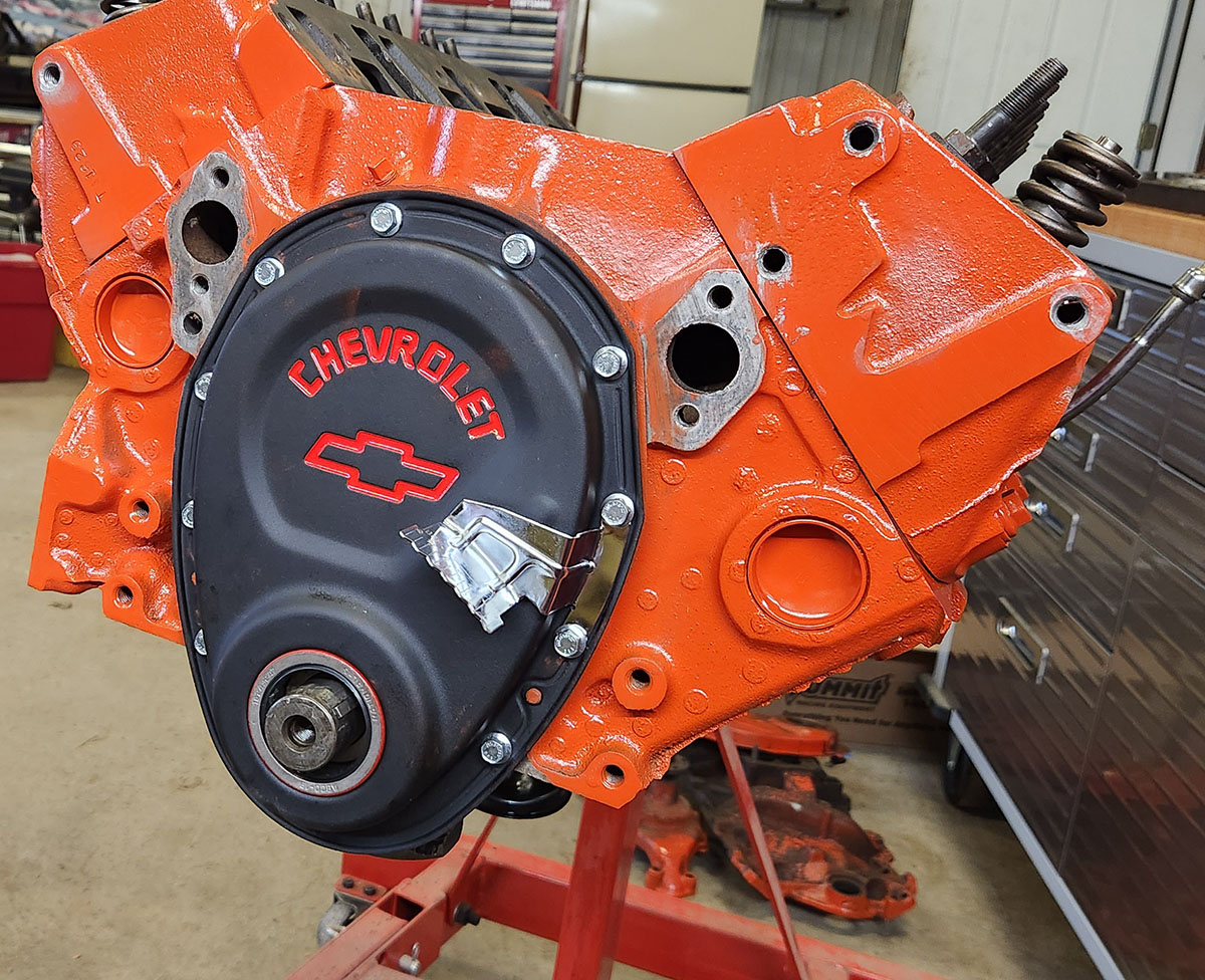
Pretty sharp, huh? We weren't sure whether to use the bright bolts (which came with the chrome timing cover we ended up not being able to use), but once we had them on, I thought they looked pretty good. Mind you, at the time I still thought we were going to be using that chrome timing pointer. More on this in a minute.
With the cover on, the next logical step was to put on the vibration damper, sometimes (a bit incorrectly) called the harmonic balancer or crankshaft counterweight. This is the big, circular weight on the very front of the crankshaft. It's actually two pieces of metal bonded together with a rubber joint, which enables it to absorb vibration as the crankshaft rotates. The crankshafts in this type of engine are internally balanced (that's what all those big metal flanges you saw on it in the piston installation episode are for), so the damper is symmetrical and doesn't do anything other than soak up stray vibrations from slightly imperfect balancing. (In some other variants of the small-block Chevy, it actually has metal removed so that it's asymmetrical and does do some balancing.)
This fits very snugly on the crankshaft nose, some it doesn't just slide on there. There are several different ways of installing it. You can heat it up so the hole expands, making it easier to slide on, but we didn't have the sort of torch available. You can just bang it on there with a hammer made of some soft metal, like lead or copper. We don't have one of those either. Or you can pull it on with a puller, which screws into the threaded hole in the end of the crankshaft and pulls the damper on as it's screwed farther in.
We didn't have one of those either, but what we do have is that huge rack full of assorted hardware. That hardware did not include a bolt with the correct fine threads, but that was OK. We had plenty that were the right major diameter (the size of the outside of the threads) and had coarse threads that didn't go all the way up.
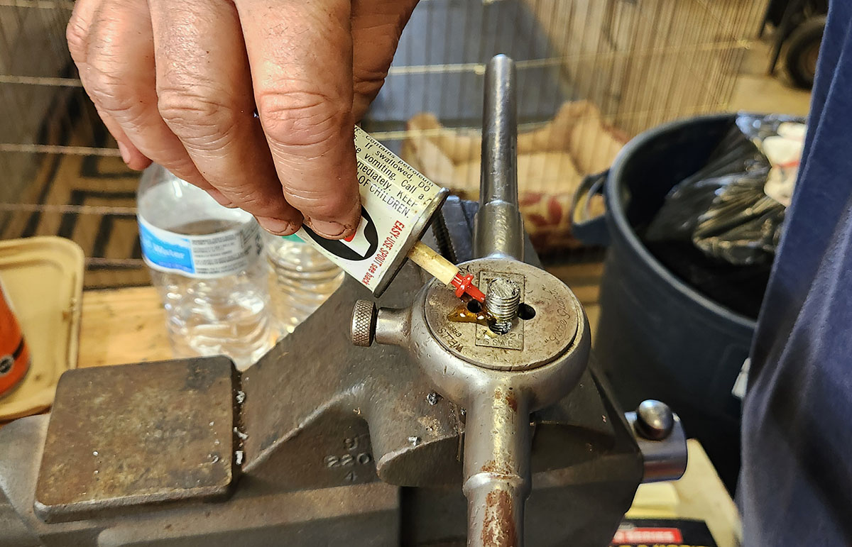
We took one of those bolts, cut the head off with a hacksaw, and then used a tap-and-die set that my father inherited from his grandfather to cut fine threads in what had been the head end. So that's pretty badass.
Then, after tapping the balancer gently on and making sure it was lined up properly with the keys on the crankshaft nose, we screwed the fine-thread end into the crank; added the big washer that's actually supposed to be there, some smaller washers for spacing, and a nut to the coarse-thread end; and carefully drove the balancer in with a socket wrench.
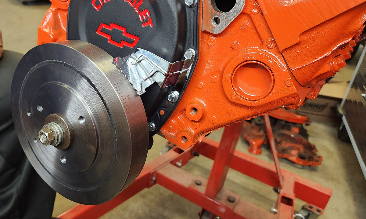
Once it was in far enough, we used a double nut to back our homemade puller out, then replaced it with the proper bolt that goes with the big washer to drive it the rest of the way... and then ran into another unexpected problem. Can you see what it is?
That pointer is supposed to work with markings on the edge of the balancer to indicate where the crankshaft is in its rotation. It's part of how you fine-tune the engine's timing. But... well...
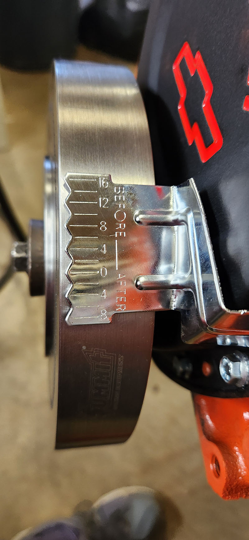
... you're not going to see much of those markings with the pointer sticking out quite that far.
We have no idea why it's like that. Possibly it was intended for use with a thicker balancer, although those generally have a smaller diameter and so wouldn't work with this style of pointer anyway. More likely it's just not quite shaped right.
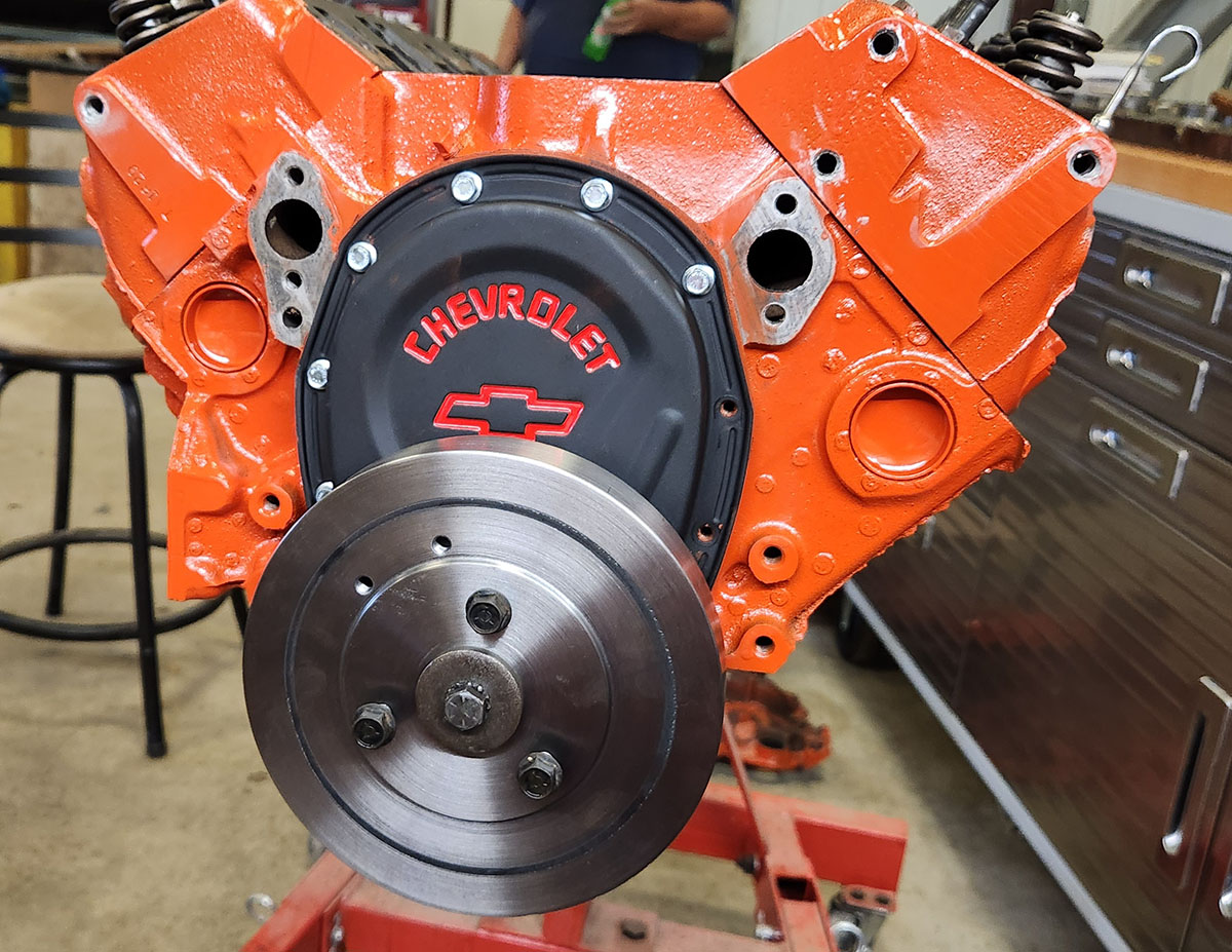
So we took it off. Fortunately, we still have the old one, which we dug out and cleaned up. While we were at it, we also found the pulley that goes on the front of the balancer, cleaned that as well, and then painted them together.
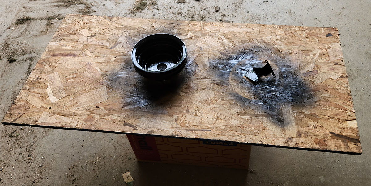
Oh, and also found the bolts that hold the pulley on, which we screwed in where they go on the balancer so as not to lose them.
So, that was session 6. Not how we expected it to go, but still well-spent time. I think I've said this before, back in the first Project Impala series, but that's a thing that happens all the time when you're working with these machines. Stuff develops, things you didn't think would work do, other things have to be ordered from far away, and you have to be flexible about your plans to make the best use of your shop time.
Hopefully the next time we get in there, we'll have the new stuff on hand and can proceed with the engine build. If not, we might take a day and put tools away, clean the bench up, take some more upstairs, and so on... which is also a valuable use of shop time, if not particularly glamorous.
--G.
-><-
Benjamin D. Hutchins, Co-Founder, Editor-in-Chief, & Forum Mod
Eyrie Productions, Unlimited http://www.eyrie-productions.com/
zgryphon at that email service Google has
Ceterum censeo Carthaginem esse delendam.

 Printer-friendly copy


