LAST EDITED ON Aug-09-24 AT 11:57 PM (EDT)
The most recent session saw some important parts installed and a bunch of general progress toward the next project goal, which is painting the engine!When last we saw the Serious Business Block, the crank and pistons had all been installed as well as the oil pump and the timing set, but there were problems with both of the available timing covers that temporarily brought operations to a halt.
In yesterday's session, the new cover had arrived, but since it has a decorative paint scheme already on it, we decided to shift gears and prep the engine for painting using some junk parts we already had on hand as masking. Before any of that could go on, though, it was time to install the cylinder heads.
The gasket between the cylinder head and the block deck is one of the most important seals on the entire engine. If it fails, the engine is basically out of service--the affected side will have poor compression and the whole engine will have lots of cooling problems, up to and including so much coolant escaping into the cylinders that it causes hydraulic damage.
As such, it's a little disconcerting that it looks and feels like nothing so much as an unusually stiff piece of cardboard.
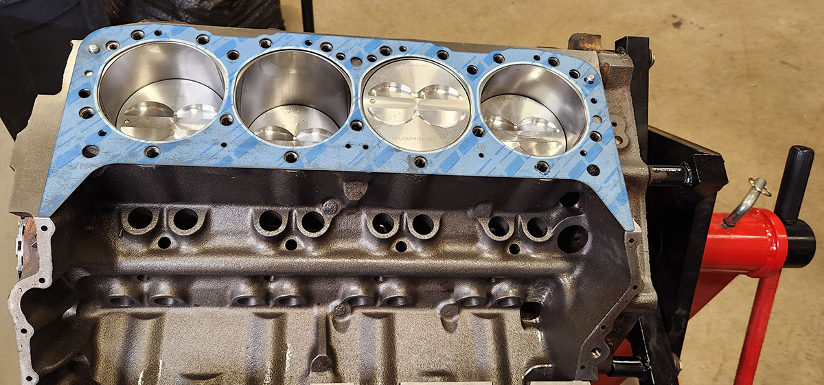
The fiber-type head gaskets like this one are a newer kind than these engines originally shipped with. The stock GM part was a metal shim that went in between the block and head with the aid of a lot of sealant on each side. These new ones are sometimes called "dry" gaskets because they require no sealant; if properly installed, they can seal up these critical joints just by being slightly crushed when the heads are torqued down. On the flip side, this makes them single-use; if you have to remove a head for any reason once the gasket is crushed, you'll have to use a new one when you put it back.
Before we put it on, this is a good opportunity to get a look at the underside of one of the actual heads we're using.
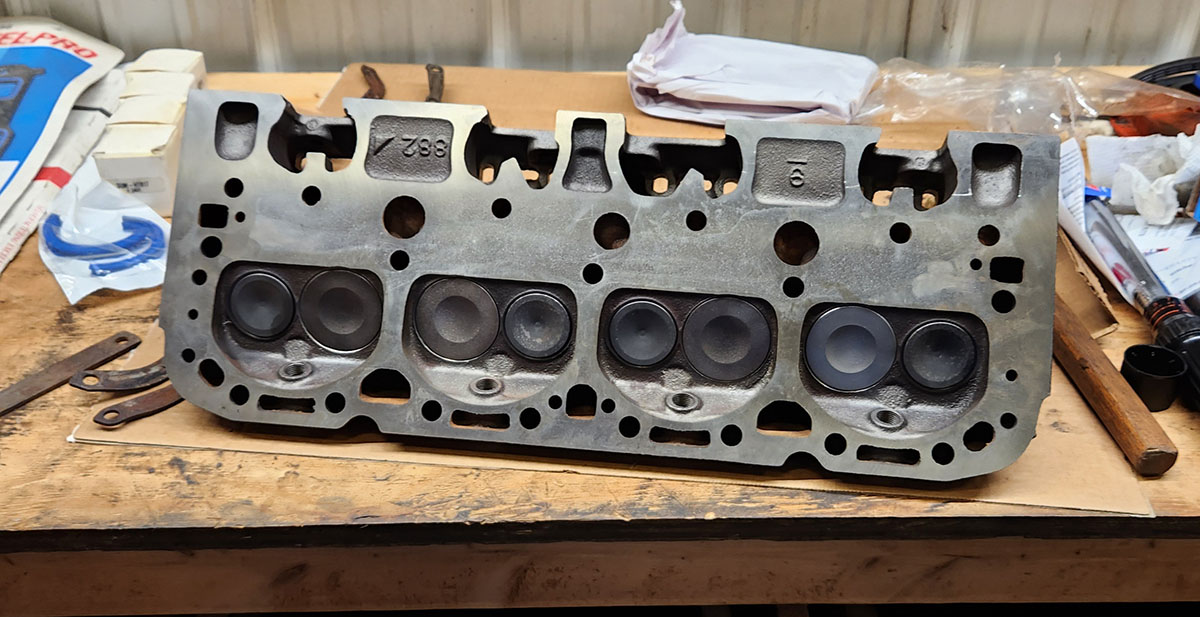
The little round holes in the combustion chambers (at the bottom in this photo) are where the tips of the spark plugs protrude through. Note the numerous oil and coolant channels, which correspond to matching ones on the block and allow fluids to circulate throughout the engine once it's all together.
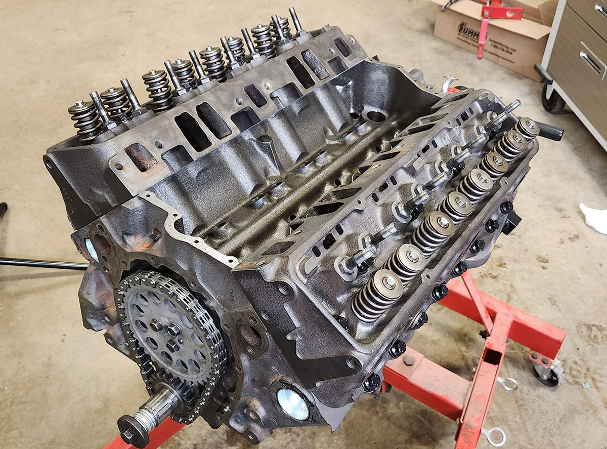
Here's a shot of the passenger side head in position but not yet bolted down.
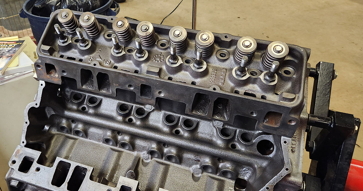
This also gives a good view of the lifter valley in between the two cylinder banks, which will be covered up by the intake manifold in the complete engine. Once everything is installed, those holes will each have a valve lifter in it, and a pushrod will connect each one to a rocker arm up above, operating one of the sprung valves. We'll have much more about this later, as the process of installing and adjusting the machinery that works the valve train is quite involved.
Once the head is properly located on its two little locating pins (visible in previous photos showing the block deck faces, including the one above of the head gasket), it's time to bolt it down. This requires no fewer than 17 bolts per head, which must be torqued down by multiple steps in a very specific order. Luckily, the part before torquing is a little more forgiving, so I could do it with my electric wrench.
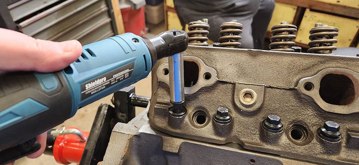
If you're curious, the final torque figure for these bolts is 70 lb-ft, and if you're following the book we're using (David Vizard's How to Rebuild Your Small-Block Chevy, 1978), must be arrived at through no fewer than three passes: one to 40 lb-ft, one to 70, and one to confirm (since tightening the later ones in the pattern to full torque the first time may relieve some of the tension on earlier ones). The order is designed to spread out the forces as evenly as possible, and at first glance seems complicated, but over the course of running it six times, I found it getting written pretty readily to short-term memory. I'm sure that someone who spends a lot of time rebuilding these engines as a matter of routine has it off by heart in short order.
With the heads installed, this thing is very much starting to look like an engine.
Next order of business was to dig an old intake manifold out of the parts hoard, clean it up in the parts washer, and install it temporarily, to cover up the lifter valley when we paint the block and heads. We have the manifold we intend to use on this engine already...
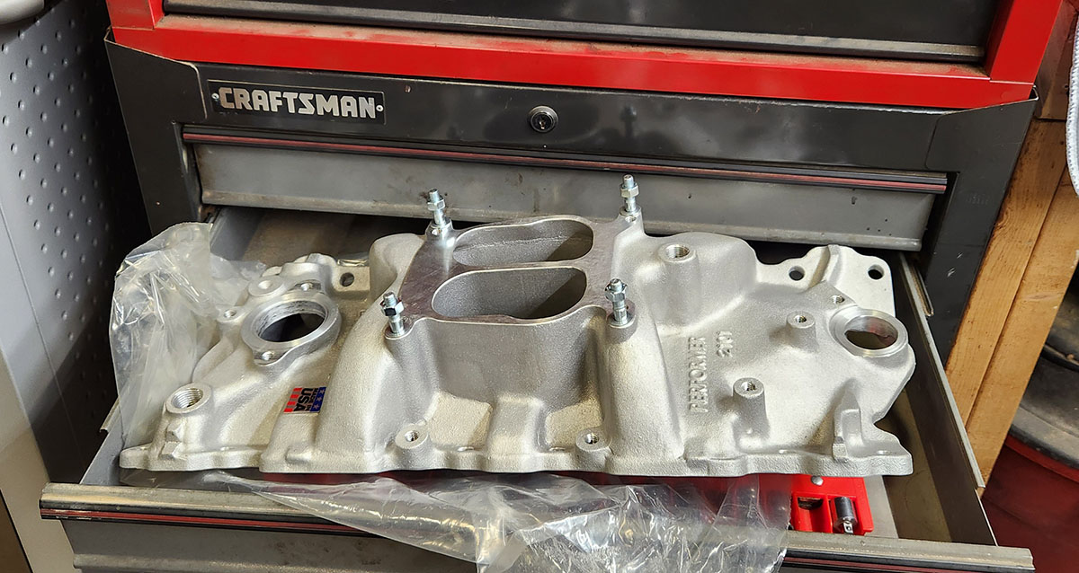
... but since it's a nice shiny aluminum Edelbrock Performer, we don't want to get paint on it. Instead, we found this old-timer.
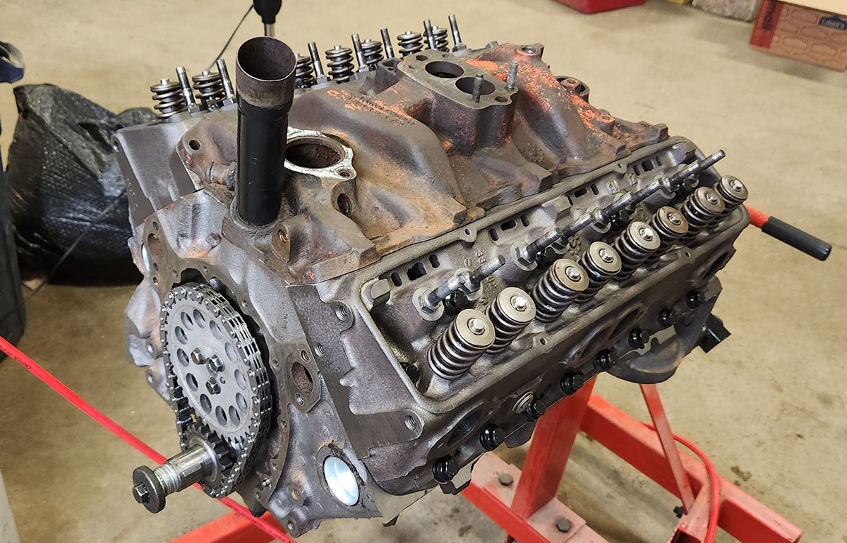
This is quite an early manifold, as it has that big black pipe on the front. That was how they did the engine oil fill on early SBCs, until someone realized that you could just pour it in through a port in one of the valve covers and it would find its way down to the crankcase from there. Also, you can see that, unlike a decoratively finished aftermarket intake, this one was painted to match the engine it was on back in the day, and still carries many traces of its original Chevy red-orange paint.
Unfortunately, when we went to bolt this old-timer down, we ran into a problem that it took us some headscratching to figure out: it didn't fit properly. We could bolt down one side or the other, but not both--fastening one side made the bolt holes in the other side not line up with their mates in the block. It was as if the manifold were slightly too big.
After puzzling over this for a bit, I realized that's because it is, or rather, the engine is slightly too small. Both the block decks and the head faces have been shaved in the process of reconditioning them--only a few thousandths of an inch, but when you're working with big chunks of cast iron, those thousandths make a difference pretty quickly. In this case, they change the contour that the manifold has to interface with...
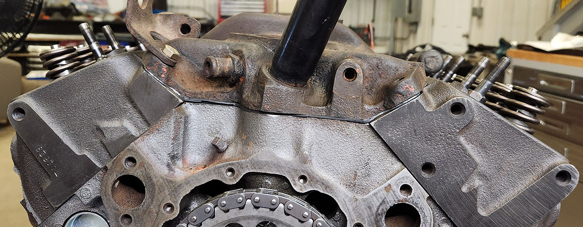
... just enough to throw off the alignment of a part, like the old manifold, that's built expecting the stock dimensions. You might not even be able to see it in the photo above, but it's enough to make fully fastening down the old manifold impossible.
Out of curiosity, I took a closer look at the aftermarket manifold we're planning to use, and sure enough...
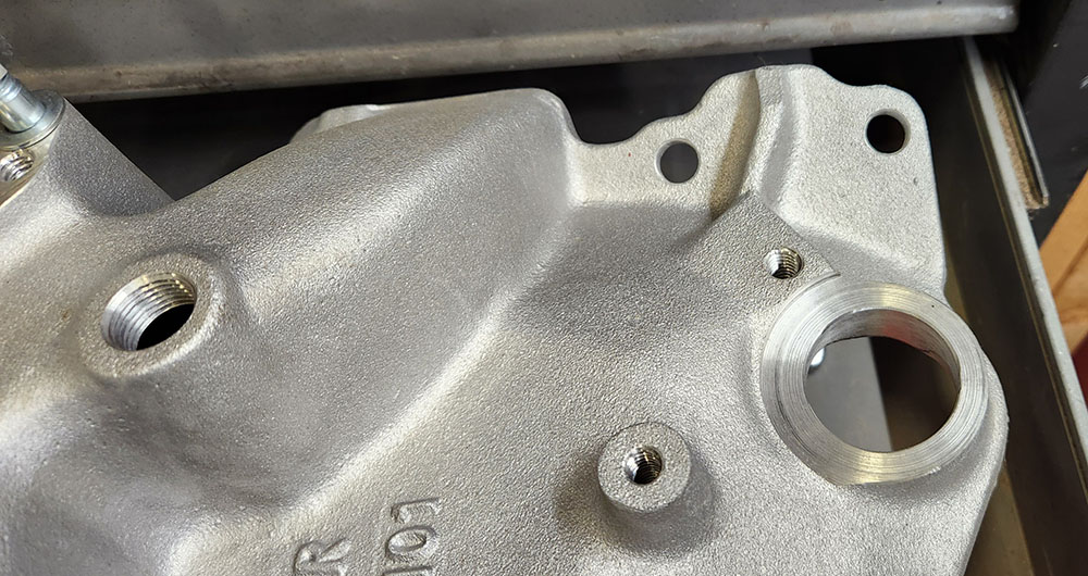
... the bolt holes in it are slightly oblong. The engineers at Edelbrock knew their manifold was going to be used on rebuilt engines, and that said engines may well have been shaved, so they designed the bolt holes to accommodate a small but critical range of valley sizes. Smart!
With a little finagling, though, we were able to get bolts into two opposite corners of the old manifold, which is enough for our purposes. We can put a bead of room-temperature vulcanization cream around the seam, which will be fine for keeping-paint-out purposes and can easily be scraped off before we put the Performer on with a real gasket/sealer combo underneath, and we've got enough bolts in to hold a couple of lifting eyes. This will come in handy when the time comes to take the whole shebang off the engine stand and do something else with it, like, say, put it in a vehicle.
When the time comes, here's what that'll look like (except hopefully without the stray water heater and table saw :).
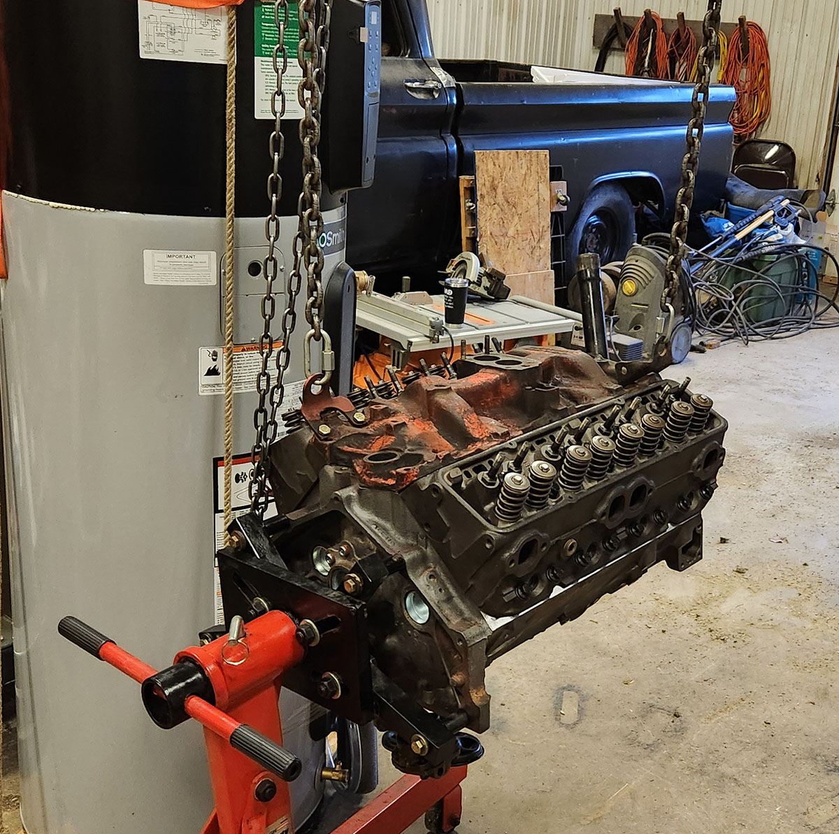
This is... well, the old man got a little paranoid after we put the heads on about how much weight the engine stand is carrying. It's designed for that, but still, he had visions of us coming back to the shop and finding engine pieces all over the floor. So now it's hooked up to the hoist, with just a little bit of tension on it, and still attached to the stand.
I think that's a little bit silly, but the scenario he envisoned would be pretty bad, so... sure, OK. :)
That's all we had time for this time. Next time, we'll put an old timing cover and oil pan and some old valve covers on there, seal it all up as best we can, and then find out if the old can of Chevy red-orange engine paint we found upstairs is any good.
--G.
-><-
Benjamin D. Hutchins, Co-Founder, Editor-in-Chief, & Forum Mod
Eyrie Productions, Unlimited http://www.eyrie-productions.com/
zgryphon at that email service Google has
Ceterum censeo Carthaginem esse delendam.

 Printer-friendly copy


